
|
|
|
|
|
try:
    import cirq
except ImportError:
    print("installing cirq...")
    !pip install --quiet cirq
    print("installed cirq.")

import cirq
import matplotlib.pyplot as plt
import numpy as np
import networkx as nx
TiltedSquareLattice
This is a grid lattice rotated 45-degrees.
This topology is based on Google devices where plaquettes consist of four qubits in a square connected to a central qubit:
x   x
  x
x   x
import itertools
from cirq import TiltedSquareLattice

side_lens = np.arange(1, 4 + 1)
l = len(side_lens)

fig, axes = plt.subplots(l, l, figsize=(3.5 * l, 3 * l))
for widthi, heighti in itertools.product(np.arange(l), repeat=2):
    width = side_lens[widthi]
    height = side_lens[heighti]
    ax = axes[heighti, widthi]
    topo = TiltedSquareLattice(width, height)
    topo.draw(ax=ax, tilted=False)

    if widthi == 0:
        ax.set_ylabel(f'Height {height}', fontsize=14)
    if heighti == l - 1:
        ax.set_xlabel(f'Width {width}', fontsize=14)

    ax.set_title(f'n = {topo.n_nodes}', fontsize=14)

fig.tight_layout()
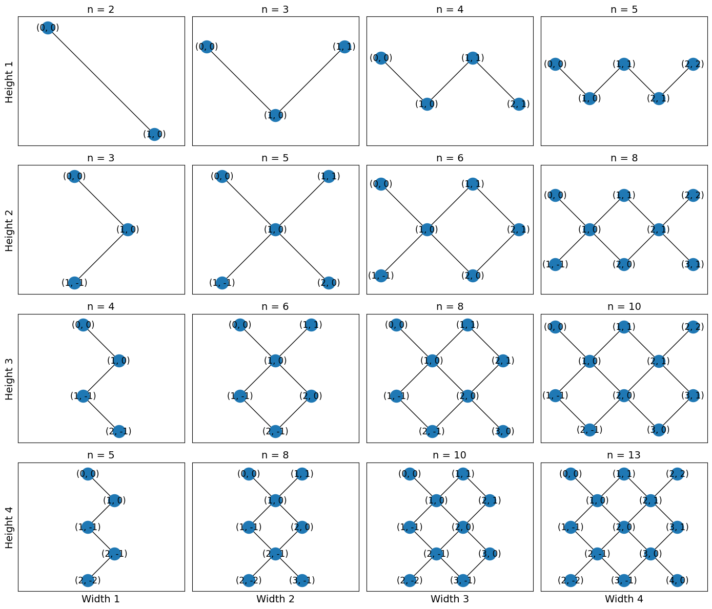
The corner nodes are not connected to each other. width and height refer to the rectangle
formed by rotating the lattice 45 degrees. width and height are measured in half-unit
cells, or equivalently half the number of central nodes.
Nodes are 2-tuples of integers which may be negative. Please see get_placements for
mapping this topology to a GridQubit Device.
Placement
import networkx as nx

SYC23_GRAPH = nx.from_edgelist(
    [
        ((3, 2), (4, 2)),
        ((4, 1), (5, 1)),
        ((4, 2), (4, 1)),
        ((4, 2), (4, 3)),
        ((4, 2), (5, 2)),
        ((4, 3), (5, 3)),
        ((5, 1), (5, 0)),
        ((5, 1), (5, 2)),
        ((5, 1), (6, 1)),
        ((5, 2), (5, 3)),
        ((5, 2), (6, 2)),
        ((5, 3), (5, 4)),
        ((5, 3), (6, 3)),
        ((5, 4), (6, 4)),
        ((6, 1), (6, 2)),
        ((6, 2), (6, 3)),
        ((6, 2), (7, 2)),
        ((6, 3), (6, 4)),
        ((6, 3), (7, 3)),
        ((6, 4), (6, 5)),
        ((6, 4), (7, 4)),
        ((6, 5), (7, 5)),
        ((7, 2), (7, 3)),
        ((7, 3), (7, 4)),
        ((7, 3), (8, 3)),
        ((7, 4), (7, 5)),
        ((7, 4), (8, 4)),
        ((7, 5), (7, 6)),
        ((7, 5), (8, 5)),
        ((8, 3), (8, 4)),
        ((8, 4), (8, 5)),
        ((8, 4), (9, 4)),
    ]
)
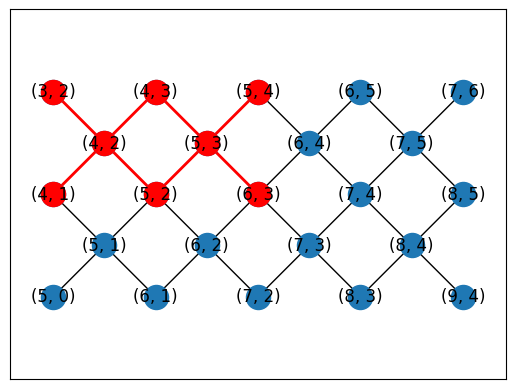
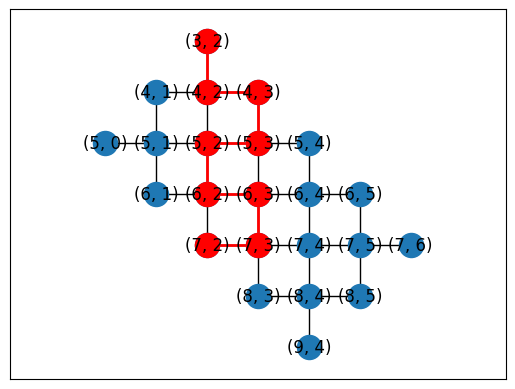
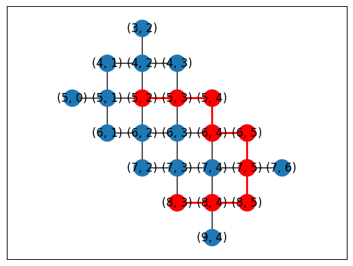
You can manually generate mappings between NamedTopology nodes and device qubits using helper functions.
topo = TiltedSquareLattice(4, 2)

cirq.draw_placements(
    SYC23_GRAPH,
    topo.graph,
    [topo.nodes_to_gridqubits(offset=(3, 2)), topo.nodes_to_gridqubits(offset=(5, 3))],
    tilted=False,
)
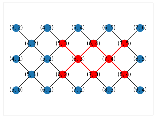
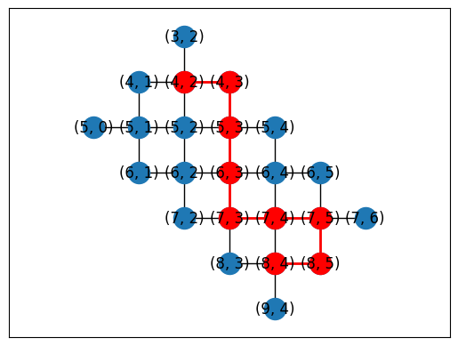
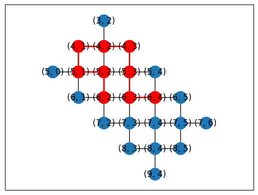
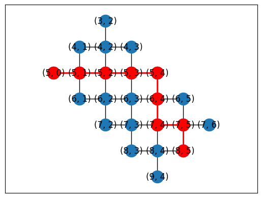
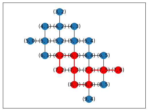
Or you can automatically generate placements using a subgraph monomorphism algorithm in NetworkX.
topo = TiltedSquareLattice(4, 2)
placements = cirq.get_placements(SYC23_GRAPH, topo.graph)
cirq.draw_placements(SYC23_GRAPH, topo.graph, placements[::3])
print('...\n')
print(f'{len(placements)} total placements')
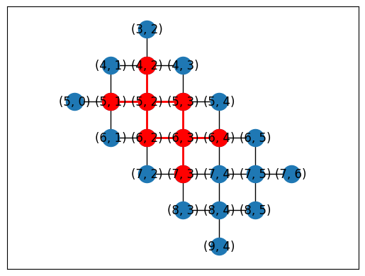
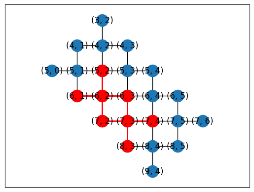
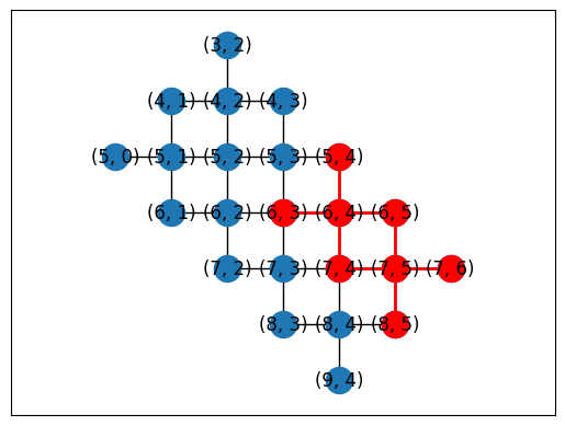
...

12 total placements
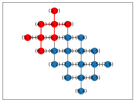
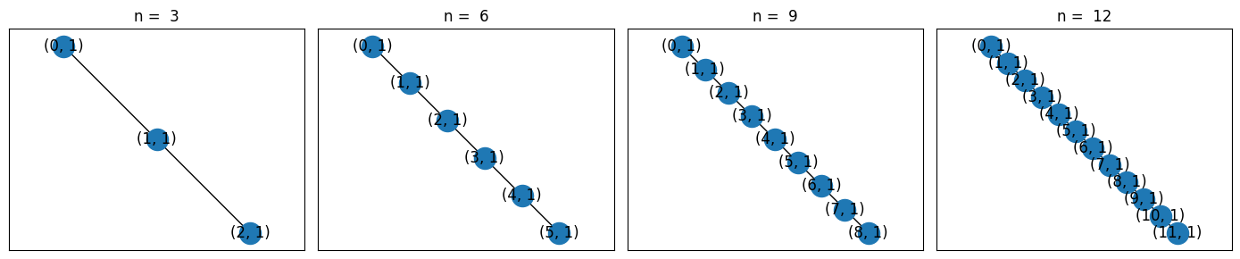
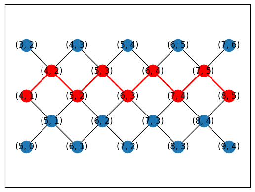
LineTopology
This is a 1D linear topology.
Node indices are contiguous integers starting from 0 with edges between adjacent integers.
from cirq import LineTopology

lens = np.arange(3, 12 + 1, 3)
l = len(lens)
fig, axes = plt.subplots(1, l, figsize=(3.5 * l, 3 * 1))

for ax, n_nodes in zip(axes, lens):
    LineTopology(n_nodes).draw(ax=ax, tilted=False)
    ax.set_title(f'n =  {n_nodes}')

fig.tight_layout()
Manual placement
topo = LineTopology(9)

cirq.draw_placements(
    SYC23_GRAPH,
    topo.graph,
    [
        {
            i: q
            for i, q in enumerate(
                [
                    cirq.GridQubit(4, 1),
                    cirq.GridQubit(4, 2),
                    cirq.GridQubit(5, 2),
                    cirq.GridQubit(5, 3),
                    cirq.GridQubit(6, 3),
                    cirq.GridQubit(6, 4),
                    cirq.GridQubit(7, 4),
                    cirq.GridQubit(7, 5),
                    cirq.GridQubit(8, 5),
                ]
            )
        }
    ],
    tilted=False,
)
Automatic placement
topo = LineTopology(9)
placements = cirq.get_placements(SYC23_GRAPH, topo.graph)
cirq.draw_placements(SYC23_GRAPH, topo.graph, placements[::300])
print('...\n')
print(f'{len(placements)} total placements')
...

1615 total placements