 View on QuantumAI View on QuantumAI
|
 Run in Google Colab Run in Google Colab
|
 View source on GitHub View source on GitHub
|
|
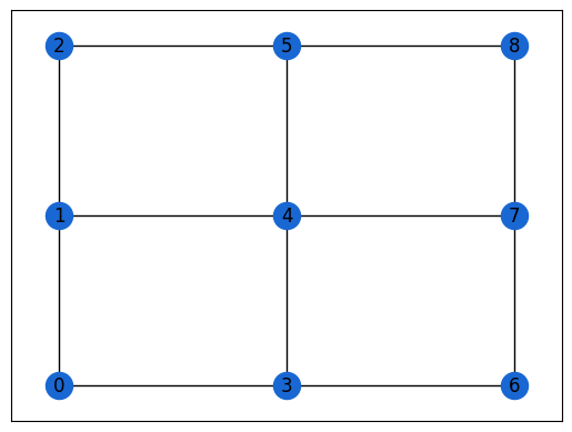
The "hardware grid" problem is defined by a Hamiltonian whose topology matches the hardware graph natively. This permits a simple compilation ("routing") with circuit depth per p-step going like \(O(1)\).
Setup
Install the ReCirq package:
try:
    import recirq
except ImportError:
    !pip install git+https://github.com/quantumlib/ReCirq
Now import Cirq, ReCirq and the module dependencies:
import cirq
import recirq

import networkx as nx
import numpy as np
from cirq.contrib.svg import SVGCircuit, circuit_to_svg

from recirq.qaoa.classical_angle_optimization import OptimizationResult
from recirq.qaoa.problems import get_all_hardware_grid_problems
Set the theme colors:
QBLUE = '#1967d2'
QRED = '#ea4335ff'
QGOLD = '#fbbc05ff'
Create a grid
Here, we'll generate a 3x3 grid with arbitrarily chosen (fake!) beta, gamma parameters.
fake_device_graph = nx.grid_2d_graph(3, 3)
fake_device_graph = nx.relabel_nodes(
    fake_device_graph, mapping={(r, c): cirq.GridQubit(r, c)
                                for r, c in fake_device_graph.nodes})

problems = get_all_hardware_grid_problems(fake_device_graph, central_qubit=cirq.GridQubit(1, 1),
                                          n_instances=10, rs=np.random.RandomState(52))
n_qubits = 9
instance_i = 0
problem = problems[n_qubits, instance_i]

optimum = OptimizationResult(p=1, f_val=None, gammas=[0.123], betas=[0.456], min_c=None, max_c=None)
nx.draw_networkx(problem.graph,
                 pos={i: problem.coordinates[i] for i in range(problem.graph.number_of_nodes())},
                 node_color=QBLUE)
If, however, you've been following along, we can load in the results of HardwareGridProblemGenerationTasks for which we've actually pre-computed the optimal angles. TODO: enable.
from recirq.qaoa.experiments.problem_generation_tasks import HardwareGridProblemGenerationTask
from recirq.qaoa.experiments.angle_precomputation_tasks import AnglePrecomputationTask

gen_task = HardwareGridProblemGenerationTask(
    dataset_id = '2020-03-19',
    device_name = 'Sycamore23',
    instance_i = 0,
    n_qubits = 5,
)

pre_task = AnglePrecomputationTask(
    dataset_id = '2020-03-23',
    generation_task = gen_task,
    p = 1,
)
print(gen_task)
print(pre_task)
from recirq.qaoa.experiments.problem_generation_tasks import DEFAULT_BASE_DIR as PGEN_BASE_DIR
from recirq.qaoa.experiments.angle_precomputation_tasks import DEFAULT_BASE_DIR as APRE_BASE_DIR

gen_data = recirq.load(gen_task, base_dir=PGEN_BASE_DIR)
pre_data = recirq.load(pre_task, base_dir=APRE_BASE_DIR)
problem = gen_data['problem']
optimum = pre_data['optimum']
print(optimum)
nx.draw_networkx(problem.graph,
                 pos={i: problem.coordinates[i] for i in range(problem.graph.number_of_nodes())},
                 node_color=QBLUE
                )
Ansatz
As always, the circuit ansatz involves \(|+\rangle\) initialization followed by alternating applications of the problem and driver unitaries. We first construct a highly abstracted circuit with these multi-qubit operations.
from recirq.qaoa.gates_and_compilation import ProblemUnitary, DriverUnitary
qubits = cirq.LineQubit.range(problem.graph.number_of_nodes())

circuit = cirq.Circuit(
    cirq.H.on_each(qubits),
    ProblemUnitary(problem.graph, gamma=optimum.gammas[0]).on(*qubits),
    DriverUnitary(len(qubits), beta=optimum.betas[0]).on(*qubits)
)
SVGCircuit(circuit)
Hardware topology
We can enact the problem unitary with four entangling layers per p-step.
- Horizontal links from even columns
- Horizontal links from odd columns
- Vertical links from even rows
- Vertical links from odd rows
To help the algorithm, we must specify coordinates to the compilation routine. This maps from bit indices \(\in \{0, 1, \dots n\}\) to (row, column) coordinates so the compilation routine can categorize the various links into the above four categories. This is a little roundabout since we'll be mapping to GridQubits, but I'm trying to emphasize the distinction between the problem (which is not related to quantum computing) and the implementation (which is).
As always, the driver unitary is nothing more than single-qubit X rotations.
from recirq.qaoa.gates_and_compilation import compile_problem_unitary_to_hardware_graph, \
                                              compile_driver_unitary_to_rx
circuit = compile_problem_unitary_to_hardware_graph(circuit, problem.coordinates)
circuit = compile_driver_unitary_to_rx(circuit)
SVGCircuit(circuit)
Compilation
To compile \(e^{i \gamma w_{ij} Z_i Z_j}\), express the ZZ interaction as three rounds of SYC gates. We take a brief aside to look at this compilation.
import numpy as np
zz = cirq.Circuit(cirq.ZZ(*qubits[:2])**(2*0.345/np.pi))
SVGCircuit(zz)
from recirq.qaoa.gates_and_compilation import compile_to_syc
zz = compile_to_syc(zz)
SVGCircuit(zz)
Function zz_as_syc is included for convenience
from recirq.qaoa.gates_and_compilation import zz_as_syc
zz = zz_as_syc(0.345, *qubits[:2])
SVGCircuit(zz)
cirq.testing.assert_allclose_up_to_global_phase(
    cirq.Circuit(cirq.ZZ(*qubits[:2])**(2*0.345/np.pi)).unitary(),
    zz_as_syc(0.345, *qubits[:2]).unitary(),
    atol=1e-8
)
cirq.testing.assert_allclose_up_to_global_phase(
    compile_to_syc(cirq.Circuit(cirq.ZZ(*qubits[:2])**(2*0.345/np.pi))).unitary(),
    zz_as_syc(0.345, *qubits[:2]).unitary(),
    atol=1e-8
)
Structure the gates
Make sure all the gates are well-structured. This means each layer is composed of homogeneous operations which are native to the device.
from recirq.qaoa.circuit_structure import validate_well_structured
_, stats = validate_well_structured(zz)
stats
HomogeneousCircuitStats(num_phx=3, num_z=3, num_syc=2, has_permutation=False, has_measurement=False)
Compiling to native operations
We use the above compilation of ZZ to compile our circuit to native operations. Because our compilation produces well-structured gates and our starting circuit was structured, the resulting circuit is well-structured.
from recirq.qaoa.gates_and_compilation import compile_to_syc
circuit = compile_to_syc(circuit)
SVGCircuit(circuit)
_, stats = validate_well_structured(circuit)
stats
HomogeneousCircuitStats(num_phx=9, num_z=9, num_syc=8, has_permutation=False, has_measurement=False)
Append measurement
mcircuit = circuit + cirq.measure(*qubits, key='z')
SVGCircuit(mcircuit)
_, stats = validate_well_structured(mcircuit)
stats
HomogeneousCircuitStats(num_phx=9, num_z=9, num_syc=8, has_permutation=False, has_measurement=True)
Compile out Z's
Z gates commute through SYC so we can remove them. This step is not necessary: the quantum operating system will track the virtual Zs if we don't remove them.
from recirq.qaoa.gates_and_compilation import compile_out_virtual_z
mcircuit = compile_out_virtual_z(mcircuit)
SVGCircuit(mcircuit)
Compile out negligible gates
We've left several PhX^0 to keep our circuits structured. As the very last compilation step, we can drop these.
from recirq.qaoa.gates_and_compilation import compile_to_non_negligible
mcircuit = compile_to_non_negligible(mcircuit)
SVGCircuit(mcircuit)
_, stats = validate_well_structured(mcircuit)
stats
HomogeneousCircuitStats(num_phx=9, num_z=0, num_syc=8, has_permutation=False, has_measurement=True)
Place on device
- Our problem has integer nodes because it should be specified independently of a quantum implementation
- Our circuit has LineQubit qubits to emphasize the fact that we can place this circuit in multiple locations on a device
- Our
coordinateslist was used only as a helper for the compilation
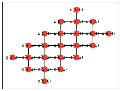
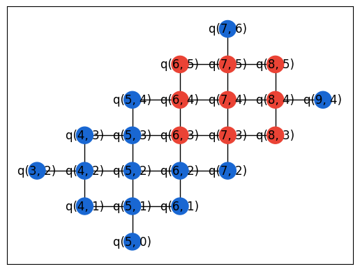
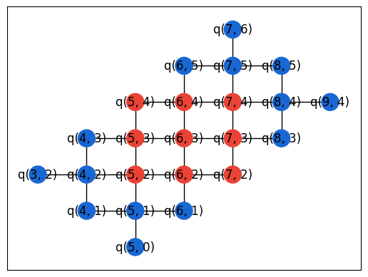
We now place the compiled circuit onto a compatible part of the device. Here, we use networkx's subgraph isomorphism routine to find all the possibilities.
from cirq.contrib.routing import gridqubits_to_graph_device
device_graph = gridqubits_to_graph_device(recirq.get_device_obj_by_name('Sycamore23').metadata.qubit_set)
nx.draw_networkx(device_graph, pos={q: (q.row, q.col) for q in device_graph.nodes}, node_color=QRED)
from matplotlib import pyplot as plt
device_graph = gridqubits_to_graph_device(recirq.get_device_obj_by_name('Sycamore23').metadata.qubit_set)
matcher = nx.algorithms.isomorphism.GraphMatcher(device_graph, problem.graph)

# There's a "rotational" freedom which we remove here:
each_set_of_qubits_only_one_subgraph = {}
for q_to_i in matcher.subgraph_isomorphisms_iter():
    each_set_of_qubits_only_one_subgraph[frozenset(q_to_i.keys())] = q_to_i

for q_to_i in each_set_of_qubits_only_one_subgraph.values():
    nx.draw_networkx(device_graph, pos={q: (q.row, q.col) for q in device_graph.nodes},
                     node_color=[QRED if q in q_to_i else QBLUE for q in device_graph.nodes])
    plt.show()
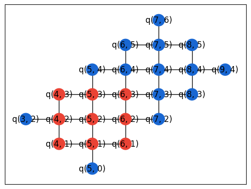
i_to_q = {i: q for q, i in q_to_i.items()}
# Since our nodes are contiguous integers starting from 0, we can flatten into a list
device_qubits = [i_to_q[i] for i in range(len(i_to_q))]
del i_to_q

def _mapq(q):
    return device_qubits[q.x]

mcircuit = mcircuit.transform_qubits(_mapq)
SVGCircuit(mcircuit)
Problem circuit functions
from recirq.qaoa.problem_circuits import get_generic_qaoa_circuit
circuit = get_generic_qaoa_circuit(
    problem_graph=problem.graph,
    qubits=qubits,
    gammas=[0.123],
    betas=[0.456],
)
SVGCircuit(circuit)
from recirq.qaoa.problem_circuits import get_routed_hardware_grid_circuit
circuit = get_routed_hardware_grid_circuit(
    problem_graph=problem.graph,
    qubits=qubits,
    coordinates=problem.coordinates,
    gammas=[0.123],
    betas=[0.456],
)
SVGCircuit(circuit)
from recirq.qaoa.problem_circuits import get_compiled_hardware_grid_circuit
circuit, qubits = get_compiled_hardware_grid_circuit(
    problem=problem,
    qubits=device_qubits,
    gammas=[0.123],
    betas=[0.456],
)
SVGCircuit(circuit)
